The 1994 Bally The Shadow is an interesting game in many aspects. It has no pop bumpers, but instead it features a lot of gadgets. And we know gadgets are the first things that break, right? :) 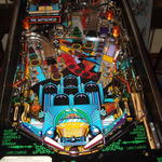
I got this machine in a non-working state. I was warned beforehand it wouldn't even boot. A quick inspection showed that the machine was nonetheless "sane": all its playfield parts were present, and the backbox didn't seem to scary, at least at first sight (more on that later). Yet, the diamond playfield (typical for WMS/Bally games from this era) was covered with an ugly mylar. There was also significant damage in the magnet area of the playfield, and everything was very dirty. Metal ramps were tainted and not shining anymore. Work on this machine was divided in two parts: the playfield cleanup and touchup, and the backbox electronics repairs. The backbox Power Driver Board 
Regulated +12V is directly derived from the +18V provided by this bridge, so it was no surprise the machine wouldn't work without it. I thus replaced it, making sure the component side soldering would be good (these bridges have a lot of current flowing through them: excellent solders are in order). I made sure the right fuses were used everywhere (people tend to over-fuse this board, which is a grave mistake. A fuse is a lot cheaper than any other component that's likely to be destroyed by an over-current condition resulting from over-fusing). Once I was confident the PDB would work fine, I put it back in the backbox and moved to the other boards. CPU Board Random resets initially made me think something was wrong with the regulated +5V circuit, but a quick check with a digital multi-meter (DMM) ruled that out: +5V was perfectly fine and stable (even more since the machine was doing absolutely nothing, with all the PDB outputs unplugged). I then tried unplugging everything from the CPU board but its power source (connector J210), without luck (sometimes, a damaged board connected to the CPU board can confuse it). At this point I removed the CPU board and took it to the workbench, powering it with a regulated digital power source. Same symptoms. But this time I had a closer look at the CPU and noticed two things:
Corrosion, in particular on sockets, can totally screw up a CPU board, I've learnt that first-hand when working on the Kiss, so I set out to replace them all, but the big square one (Note: I've already explained elsewhere how to remove sockets). I gently sanded the pins of the square one, as well as all the pins of the above mentioned chips, to clean them from corrosion. Note: you need a PLCC extractor to remove the ASIC, or you're almost certain to wreck both the chip and the socket. The pictures of the process can be found here: 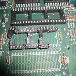
Once this was done, I replaced the chips in the new sockets and tried to boot the board on the workbench. It worked immediately. Problem solved, putting it back to the backbox, and moving to the next one: the DMC. Dot Matrix Controller Howto fix things when logic goes wrong I then plugged the ribbons back into the DMC board, and checked for the signals (addresses, data and clock) on the board itself, typically at U7, U1, U2, U3, etc. Inputs were still good. I then moved on to the next step: key signals generated by the early stages of the board's logic chips, starting with local clock signals coming from U7. I didn't have to go very far: pins 2 and 7 were showing nothing but very low level noise. That meant only one thing: these signals were grounded. I took the board off to the workbench, and a quick test with the DMM in "buzz" mode confirmed the diagnostic: nice "beeeeep" between either pin 2 or 7 and the ground plane. The next question obviously was: where does the grounding happen? In fact, several chips share the E clock generated by U7 (which by the way explains why nothing was working), and it could have been any of them failing (I did a visual check to rule out shortcuts on the board's tracks). Now, I didn't really feel like desoldering each of the chips one by one until I found the right one, so I used a "seek and destroy" approach, with a little bit of added logic: the most likely to fail components are those closer to the "outside" on a board. "Outside" here means "signals coming from the outside". In other words, in the case of the DMC, and according to the schematics, I would start with U7, and then U3, U10 and going "down" in the chain. Instead of desoldering to test, I would simply "isolate" the suspect by cutting its ground track, testing, and if it still buzzed, for added security, cut the "E" track going to it as well. Turned out I was spot on: U7 was the culprit (internally shorted), so I removed it and replaced it, before fixing the tracks that I had cleanly cut, see these pictures: 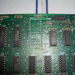
Note: U7 is a 74HCT240N. It's an "upgraded", CMOS version of the 74LS240N buffer/line driver, with faster commutation times and slightly lower power consumption. If you don't have that part handy, a 74LS240N will work just fine here. As a matter of fact, this chip is used as a buffer for the inputs coming from the CPU board, which uses LS versions of buffers on it's outputs at U1-U3, so the 74LS240 can cope with the signals that are fed by the ribbons just fine. I'm guessing Williams started using HCT versions on its DMC just because they were getting more mainstream and probably cheaper. If you don't believe that it works, check the pictures out! With this, work in the backbox was over, everything worked nicely. The playfield 
Elsewhere on the playfield, a few wires were cut as well, screws were missing and dirt was everywhere, the ramps were lackluster, some plastics were wrapped in mylar to fix breakage, and there was that ugly mylar: 
There again, the task was split in two: dealing with mini-playfield issues, and with main playfield ones. Mini-playfield 
I could fix the post, but it left a scar in the playfield, meaning that as soon as I would put it back and hook a rubber to it, it would most likely bend again: 
The solution was to fill the dent with epoxy glue, let it harden long enough and then put the post back in place. 
Unfortunately, the screws holding the coil assembly were loose and couldn't be held in place with a screwdriver since they were supposed to be soldered to the target chassis: 
Here again, epoxy came to the rescue, thanks to its very high torque resistance. I simply "soldered" the screws to the chassis with a fair amount of epoxy glue: 
Next, the mini-playfield kicker support axis was rusted: a good sanding and a tiny bit of teflon lube, and voila, the kicker works just fine and without a nasty creaking. Done! Mini-playfield now working! Main playfield 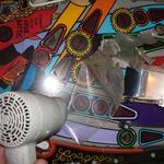
While there, I prepared to touchup the damage in the magnet area, near the "Sanctum", which can be seen here: 
It was a mess of dry residue of glue and stitches of mylar. The glue was of a different kind and dry enough that it required warming up with the hair dryer, and the use of acetone instead of meths to clean it up. Once cleaned and with the mylar stitches removed, I got this: 
As for my previous playfield touchup work on the Whoopee, I first levelled the hole with filler coating: 
Then I tried to achieve the exact same color as the playfield. I used a drop of black mixed with white, and a speck of yellow to make it slightly "dirty", matching the playfield tone a lot better: 
Note: unpolished acrylic paint doesn't react to flash light in a way that reflects the actual color of the painting under normal lighting conditions. Once this was done, and dry, I added a generous amount of mylar to cover the area and protect it from further damage. Note: perfect levelling is very important: the way the magnet works, to throw the ball into the Sanctum lock, it simply releases the ball for a brief instant, enough for the ball to move a notch downwards, and then the magnet brutally and very briefly kicks back in full force, drawing the ball towards it, and on its momentum (the magnet being turned off almost immediately) it will enter the lock. Thus, if the playfield isn't level enough, the ball will not move downward fast enough, and the process will not work at all. In the meantime, I also cleaned up the metal ramps. Products for cleaning silverware work just fine for this task! Look:
I think it's self-explanatory :-) I also cleaned up the plastics with dish-soap (let them soak for a night, then use an old toothbrush to finish the work, and rinse). Once they were clean, I repaired them using epoxy glue. Epoxy is better than cyanoacrylate (a.k.a Super Glue) in this case for two primary reasons: it can endure high temperatures, and very important, it has a much better mechanical resistance to vibrations, impacts and and shearing. I took the opportunity to replace broken lamps and put new rubbers everywhere. Once everything was back in place, it was time to do a first test of the machine. It quickly turned out the auto launcher wasn't working properly. Quite often, the ball wasn't kicked hard enough to climb the ramp, although the kicker was firmly screwed to the playfield. The problem lied elsewhere: First, it was slightly misaligned, second, and much more important, the screws holding the coil in place into the chassis were a bit loose, and the coil had some play. The consequence was that not the full force of the coil was transferred to the plunger, and the ball wasn't kicked as hard as it should have been. Watch this picture: 
The arrow on the left shows you the screws that must be very firmly tightened, whilst the coil holder is just as firmly held as tight as possible against the coil (upward, on this picture), so that it has as little play as possible. The top arrow shows how to properly align the plunger with the playfield, using the slit as reference. And voila, I replaced the black and orange decals from the battlefield and purbahs, did a final cleanup and polish, and the machine works perfectly and is so much fun to play!
|
|||
PinballsStories of little silver balls |
LanguagesNavigation |
|


|
|